 Clirik






Rechercher
To solve the abnormal heating and noise of the reducer of vertical mill (vertical roller mill) and the frequent pressure drop of hydraulic system, the core is to immediately find out the two major problems of “partial load of thrust pad” and “failure of nitrogen bladder of accumulator. Once these two fatal injuries are misjudged, the end result is often planetary gear teeth or grinding roller cracking. You know, one hour of downtime, the loss is tens of thousands of real money. If you want to find out the real cause, the only dead reason is to check the back pressure curve of the hydraulic cylinder and the vibration speed of the input shaft of the reducer (mm/s). The following set of advanced troubleshooting logic and hard core maintenance parameters were actually summarized by original factory (OEM) level overhaul experts on site.
The complex failure of vertical mill is never isolated. To accurately lock the source of the fault, you must cling to the “V-P-T” (vibration, pressure, temperature) this troubleshooting framework.
The first step: check the pressure (Pressure). The dynamic pressure difference between the tension pressure set by the hydraulic system and the actual build-up pressure directly determines the stability of the grinding disc bed. Once the material bed is unstable, the huge impact force will hit the yellow dragon along the grinding disc and hit the reducer.
The second step: stare at temperature (Temperature). If the RTD temperature measuring probe buried in the thrust tile babuton alloy has an instantaneous temperature surge (over 65°C), there is no doubt that the fluid power oil film is definitely broken, or the force on the hydraulic pull rod is seriously uneven.
Step 3: Grasp the vibration (Vibration). Call up the high frequency map of the reducer box. As long as you see the peak of the gear mesh frequency (GMF) tied up like a nail, and accompanied by a dense side band, this is the final conclusion-the tooth surface has undergone irreversible plastic deformation.
To deal with the failure of the vertical mill reducer, it is necessary to make a fuss on the two lines of “bearing” and “lubrication” at the same time. Under the limit of dynamic load, any micron level geometric tolerance deviation will be infinitely enlarged.
Burning tile culprit, is the fluid power oil film instant collapse. Once the mill swallows large pieces of hard ore, or the thickness of the material bed suddenly falls, the instantaneous impact load can easily pierce the micron-sized oil film between the thrust tile and the mill base.
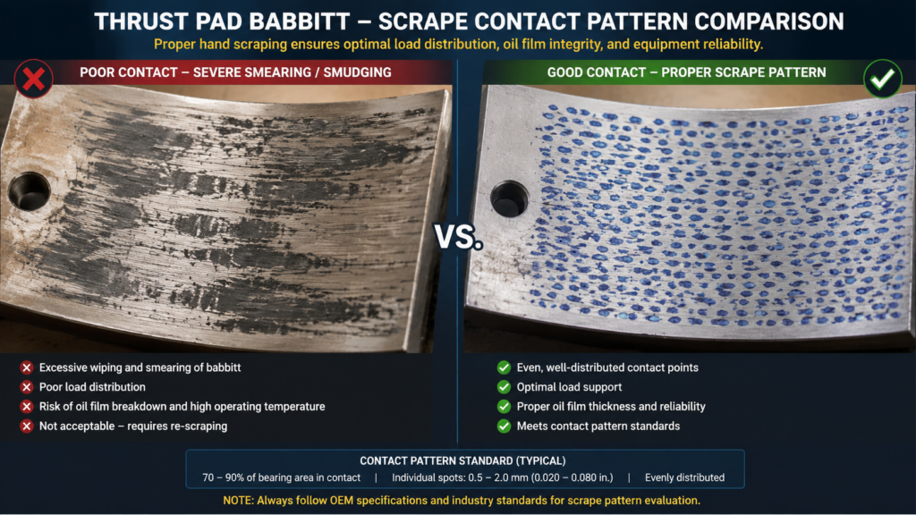
At this time, the filter element of the lubrication station of the reducer must be sampled immediately. If you can see shiny babbit chips with the naked eye, don’t hesitate to stop and open the box immediately. The iron law for on-site emergency repair is: when the contact surface is scraped with Prussian blue, it must be ensured that the thrust tile has not less than 3 to 4 contact points per square centimeter. The height difference of all tiles after installation must be stuck within 0.02mm. Once this extreme value exceeds the standard, a single tile will bear twice the axial force, and the tile will be burned again as soon as the machine is started.
The micro pitting of planetary gear stage is often caused by oil particle pollution and contact stress overload. Although micro-pitting will not cause the gear to collapse immediately, it will permanently damage the involute tooth profile, making the machine emit extremely harsh high-frequency squealing.
Take the oil particle size detection (ISO 4406) data to speak is the most accurate. If the ISO code crosses the red line of 18/16/13, abrasive wear is gnawing at the tooth surface. The first aid method on site is by no means blindly changing gears, but immediately pulling an offline vacuum dehydration oil filter with a precision of 3 microns and replacing it with high viscosity fully synthetic gear oil (such as ISO VG 320) rich in extreme pressure (EP) additives. For those teeth that have visible peeling, chamfer the edges with a portable precision grinding tool. This step is to erase the local stress concentration point and prevent the crack from spreading all the way to the tooth root.
| Defect / Fault Type | Dominant Frequency Parameters | Spectrum Characteristics & Surges | Diagnostic Notes & Corrective Actions |
| Unbalance | 1X (Shaft Running Speed) | Surge in 1X radial amplitude. Low axial vibration. Higher harmonics (2X, 3X) are typically very low or non-existent. | Primarily caused by mass eccentricity on the gear or shaft. Addressed by precision rotor balancing. |
| Misalignment | 1X, 2X | Surge in 2X radial vibration or elevated 1X / 2X axial vibration. High axial-to-radial vibration ratio. | Indicates angular or parallel misalignment. Corrected via precision laser shaft alignment. |
| Broken Teeth | GMF & 1X Sidebands | Surge in Gear Mesh Frequency (GMF) amplitude. Presence of distinct 1X sidebands around GMF. Time waveform shows prominent 1X impact pulses. | Severe structural failure. For teeth showing macroscopic spalling prior to full breakage, use portable precision grinding tools for chamfering edges to eliminate localized stress concentration points and prevent root cracks. |
| Micro-Pitting / Pitting | GMF & High-Frequency Harmonics | Intense surge in GMF and its high-frequency harmonics, triggering characteristic high-frequency whining due to permanently altered involute gear profiles. | Originates from contact stress overload and particulate contamination. Baseline diagnosis: ISO 4406 oil particle count exceeds 18/16/13. Field Fix: Immediately deploy an offline 3-micron vacuum dehydration oil purifier and upgrade to high-viscosity full-synthetic gear oil (e.g., ISO VG 320) with Extreme Pressure (EP) additives. |
The hydraulic system is the “muscle” of the vertical mill “. Its bounden duty is to output a steady taut force and swallow the violent vibration generated during the grinding process. If the system cannot hold pressure, or the oil pump starts and stops frequently, it is a direct warning before the total collapse.
Accumulator leakage of nitrogen will create a very deceptive “ghost vibration” in the whole mill structure “. Once the accumulator bladder ruptures or the nitrogen pre-charge pressure runs out, the hydraulic cylinder completely loses the buffering and life-saving effect of the “gas spring. In this case, all the material resistance encountered by the grinding roller will become a hard mechanical impact, directly hitting the foundation and reducer. Field personnel are often fooled by this phenomenon and mistakenly believe that the reducer is seriously injured.
In case of this, it is necessary to stop the machine immediately and connect the nitrogen charging tool to measure the static pressure. The normal nitrogen pre-charge pressure must be between 60% and 70% of the working pressure (usually between 60 and 80 bar, depending on the mill model). If you press the valve core of the leather bag and the hydraulic oil is sprayed out, it means that the leather bag has been completely scrapped. When changing the new skin bag, please remember that you must apply a layer of hydraulic oil of the same brand as the system before putting it in, so as not to twist and knot the skin bag and tear yourself apart at the beginning of inflation.
Once the proportional servo valve is stuck, the tension pressure of several grinding rollers will immediately lose balance, which directly leads to serious mechanical shaking of the mill. The real killer behind the card valve is actually the paint film generated by thermal degradation and oxidation of hydraulic oil. This stuff is like superglue. Conventional mechanical pipeline filters can’t stop it.
The first step to check this problem is to measure the hysteresis curve between the servo valve coil control current and the actual spool displacement. If the lag rate exceeds 5%, it can be basically concluded that the precision valve core has been locked by the paint film. The most drastic way to draw the salary is to connect a set of electrostatic oil filter system, directly suck out the submicron oxide in the oil at the molecular level, and forcibly press the microporous filter membrane colorimetric (MPC) index below 15. Don’t use those irritating chemical solvents to violently flush the precision valve core, which will only destroy its micron-level matching clearance.
After the reducer and hydraulic system are repaired, the “dynamic load balance” must be passed before the full load is put into production. After replacing the hydraulic cylinder seal or rematching the thrust bearing of the reducer, it is absolutely forbidden to directly pull up the hydraulic tension force under no-load condition.
You have to honestly go through the ladder loading process. After the main motor is started, first give a 30% initial hydraulic tension force, and then keep the pressure for 15 minutes for every 10% increase. During this running-in period, there are two sets of data that must be closely watched: first, the hydraulic cylinder pressure difference on the diagonal must be fixed within 2 bar; Second, the vibrometer data on the input and output bearing seat of the reducer must be far below the life and death line of 4.5 mm/s. As long as one of these two items is out of line, immediately release the pressure, stop the machine, and then honestly calibrate the mechanical levelness of the tension rod again.
It must be measured with complete pressure relief on the hydraulic side. Stop the hydraulic pump first, open the oil return check valve, and completely vent the oil cylinder pressure to an absolute 0 bar. At this time, the nitrogen charging test tool is connected to the gas valve on the top of the accumulator, and what is read is the most real static nitrogen pre-charge pressure. If the pressure is measured, the measured data are all false height data, and there is no leakage at all.
The most direct reasons are nothing more than these: the cooler tube bundle is blocked by scale, the circulation cannot keep up due to the discount of the aging flow of the oil pump, or the thrust tile is dry friction due to partial load. When checking, first look at the temperature difference between the inlet and outlet of the shell and tube heat exchanger. If the temperature difference falls below 5°C, it means that the cooler is either seriously fouled or air-blocked, and pickling or exhaust shall be arranged immediately.
This indicates that there is serious oil flow inside the oil cylinder, or the hydraulic control check valve is not sealed tightly. A pressure holding test can force out the fault: push the hydraulic cylinder to a height, lock it mechanically, and then loosen the oil pipe joint with the rod cavity 1 a seam. If the joint has been dripping oil, it is the piston seal (such as the Glaire ring or the seal) completely finished. If the oil does not leak, remove the pressure retaining valve on the control valve block for cleaning.
According to ISO 10816 standard, for this heavy-duty vertical mill reducer, the effective value (RMS) of the vibration speed of the box body is perfect below 2.8 mm/s, 4.5 mm/s is the alarm red line, once it crosses 7.1 mm/s, let alone stop immediately. At ordinary times, more attention is focused on the shock pulse (Shock Pulse) peak on the spectrogram, which can expose microcracks in the bearing 3 months ahead of the overall vibration speed exceeding the standard.
The hydraulic system of the vertical mill relies on a highly sensitive proportional valve to eat, so the oil cleanliness must firmly bite the 16/14/11 of ISO 4406 standard, even cleaner. If the on-site sampling inspection finds that the particles larger than 4 microns exceed the standard, immediately push the external high-pressure circulation bypass oil filter truck to start up until it reaches the standard, otherwise the roller lifting cylinder will definitely get stuck.
Can be repaired, but only if there are slight scratches on the surface. The on-site master can manually scrape and grind the babbitt alloy layer with a special scraper to save the oil groove and the high-precision contact surface. However, if the babbitt alloy falls off, delaminates in a large area, or melts at high temperature (burns), the whole set of thrust tiles must be packaged and sent to a professional repair shop, and the babbitt alloy must be re-poured and ultrasonic flaw detection must be performed. You can’t do this kind of hot repair on the mill site.