 Clirik






Rechercher
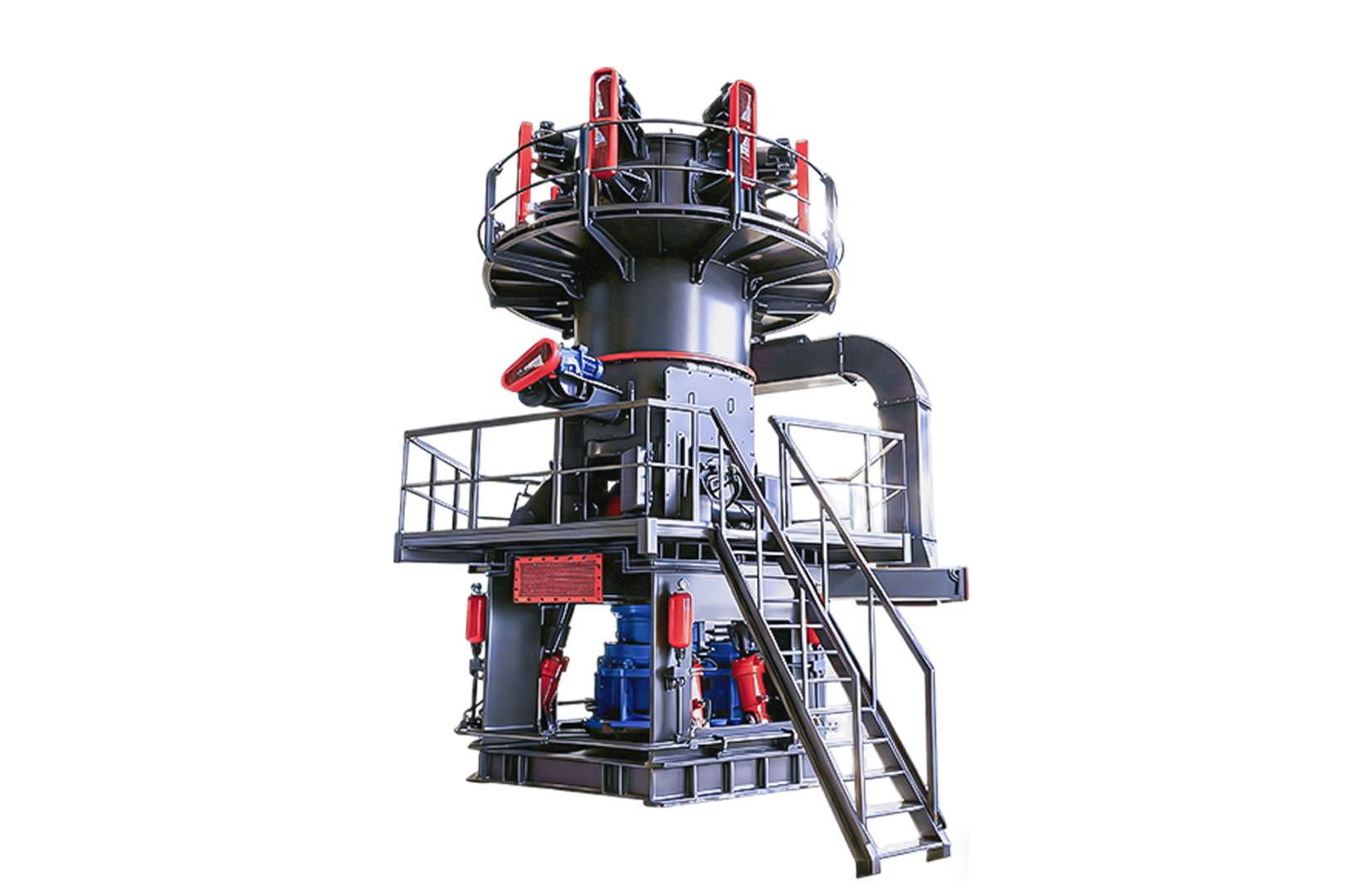
The core operating mechanism of the vertical roller mill (VRM, vertical mill for short) is based on the principle of “material bed grinding”: the grinding roller exerts a specific hydraulic force on the rotating grinding disc, thereby squeezing and crushing the raw material. From the core design point of view, the vertical mill cleverly integrates crushing, grinding, drying, dynamic powder selection and material transportation in a continuous and closed system. However, in practice, engineers in many factories are often bothered by the two problems of “high vibration jump” and “high specific energy consumption (SEC). In fact, as long as the internal structural parameters of the knife-especially to adjust the hydraulic loading curve, optimize the air spray ring gas flow rate and improve the geometry of the powder separator-can directly break through these operating bottlenecks.
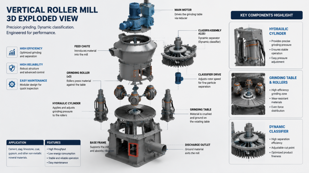
Crushing materials inside the vertical mill requires extremely precise control of extrusion and shear forces. Remember that the equipment does not rely on direct “hard-hitting” metal contact between the grinding roller and the grinding disc to crush the particles. The normal operation of the vertical mill depends on maintaining a stable and dynamic “material bed” between the grinding parts “.
If you want to really play with the vertical mill operation, you must understand the so-called “T.P.G. grinding triangle”: tension (Tension), pressure (Pressure) and gap (Gap).
Tension (hydraulic pressure): The hydraulic cylinder is responsible for applying downward pressure to the grinding roller. The higher the pulling force, the higher the grinding efficiency, but it also means that the power consumption of the main drive motor will soar exponentially. Therefore, the operator must match the hydraulic pressure curve with extreme precision according to the Bond Work Index (BWI) of the material.
Pressure (gas flow dynamics): high-speed hot air will enter the mill through the jet ring surrounding the mill. The effect of this air flow is to lift the crushed particles upwards. If the wind speed is not enough, the material will fall back in a large area, which will not only cause the grinding disc to overload, but also cause the motor current to soar instantly.
Gap (roller disc gap): The mechanical retaining ring at the edge of the grinding disc determines the thickness of the material bed. The gap between the grinding roller and the grinding disc must be strictly proportional to the maximum feed particle size. If the gap is stuck too dead and the material bed is completely pressed through, it will cause extremely serious metal friction and severe vibration of the equipment.
Each component of the modern vertical mill architecture is responsible for specific mechanical stress and fluid dynamics requirements. When selecting the type, the engineer must determine the most accurate profile parameters based on the abrasiveness and moisture content of the target material.
The shape of the roller and the grinding disc directly determines the proportional distribution of the extrusion force to the shear force. The convex grinding roller is equipped with a grooved grinding disc, which can firmly lock the material and form a restricted material bed. This ingenious design entraps the particles in it, forcing them to squeeze and rub against each other (I. e., self-grinding), rather than simply dry grinding on cast iron components. In contrast, the flat-bottomed disc design can generate greater shear force, which is very suitable for grinding soft materials such as coal, while the curved tire tread design is better at dealing with hard clinker and slag.
The hydraulic spring system plays a dual role in the mill: it is both the “generator” of the crushing force and the “shock absorber” of the mechanical shock “. The accumulator pre-charged with nitrogen is directly connected to the hydraulic cylinder. When the mill is mixed with foreign matter that cannot be crushed (such as scrap iron), the nitrogen bladder will be compressed instantly. This rapid compression allows the grinding roller to be lifted immediately, thus avoiding catastrophic damage to the gearbox.
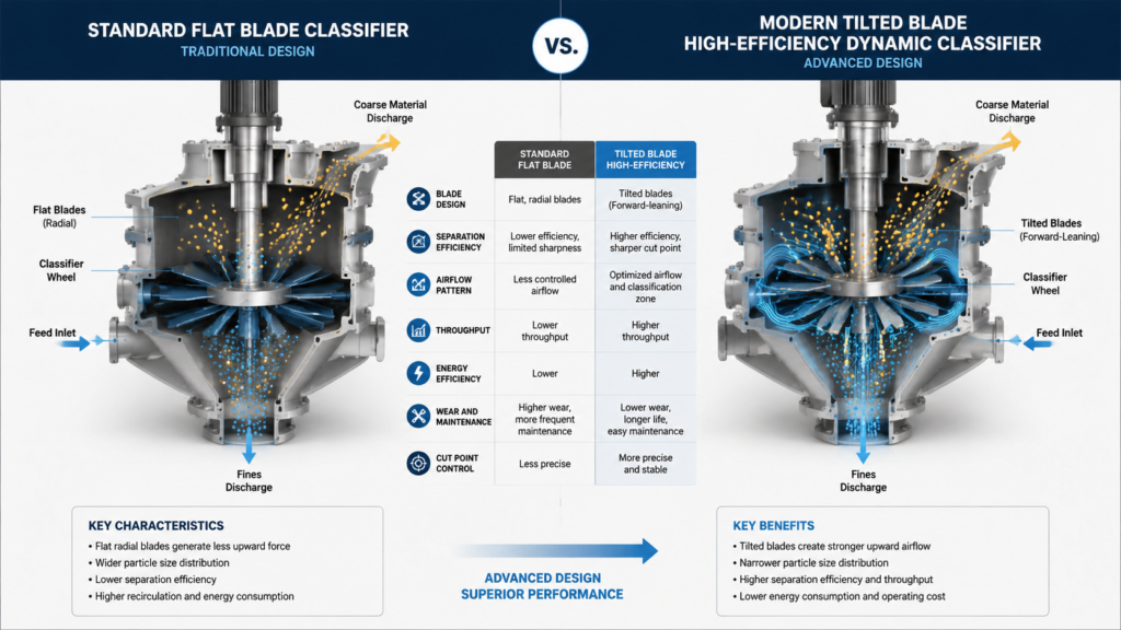
The dynamic separator can be said to be the “brain” that controls the fineness of the final product (specific surface area, Blaine) and the internal circulation rate “. The variable speed rotor blades rotate at high speed at the top of the mill housing. Once the coarse particles hit these blades, they lose their kinetic energy and fall back down the return cone to the grinding disc. Today’s advanced rotor designs usually use inclined blades, which can minimize the pressure drop across the separator, thereby greatly reducing the power consumption of the main induced draft fan (ID fan).
Textbooks or operating manuals often rarely touch on the intricate interaction between mechanical wear and process parameters. In the field, technicians often fall into some recurring “operation traps”, the appearance of these traps is often easy to be misjudged as other unrelated system failures.
High vibration in the mill is often not due to an unstable material bed, but rather to insufficient nitrogen precharge pressure in the accumulator. However, operators often misinterpret this severe vibration as “overfeeding” and consequently reduce production without proper diagnosis. The feeding 1 is small, and the material bed becomes thinner. If, at this moment, the nitrogen cushion lacks sufficient pressure to absorb the impact, the grinding roller will directly penetrate the thin material bed and slam hard onto the grinding table. Therefore, the maintenance team must test the basic nitrogen pre-charge pressure separately every week with the working hydraulic pressure cut off.
Mechanical wear of the grinding disc and grinding rollers can subtly alter the originally designed airflow dynamics. As the material‑retaining ring wears down and becomes progressively shorter, the material bed also thins, causing the material to be prematurely thrown into the jet‑air ring zone. Many plant managers are accustomed to replacing grinding rollers based solely on “operating hours,” while neglecting precise measurements of the geometric wear profile. In fact, by conducting a 3D laser scan during scheduled shutdowns for maintenance, you can obtain precise wear‑matrix data. With this information, engineers can recalibrate the hydraulic loading curve and compensate for any deformed geometry.
Optimizing internal fluid dynamics often yields a significantly higher return on investment (ROI) than investing heavily in upgrading the main motor. In Germany, a cement plant once faced an astonishing specific energy consumption of as much as 34 kWh/t during clinker grinding. The plant’s engineering team performed a minor “surgical” modification to the internal design of the vertical mill: they installed a blanking plate in the air ring, thereby increasing the internal airflow velocity directly from 35 m/s to 45 m/s.
Just this small aerodynamic action completely eliminates the stubborn problem of repeated falling cycles of internal materials.
| Technical Parameter | Before Nozzle Ring Modification | After Nozzle Ring Modification | Net Improvement |
| Nozzle Ring Gas Velocity | 35 m/s | 45 m/s | + 28.5% |
| Internal Circulation Load | 450% | 210% | – 53.3% |
| Consommation d'énergie spécifique | 34.2 kWh/t | 26.8 kWh/t | – 21.6% |
| Stable Mill Output (t/h) | 145 t/h | 170 t/h | + 17.2% |
The data will not lie: the efficiency of the vertical mill depends entirely on whether the mechanical crushing force and the aerodynamic lifting force can achieve perfect co-frequency resonance.
The ideal material bed thickness is typically maintained between 1% and 2% of the grinding roller diameter. For example, if the diameter of the grinding roller is 2 meters, the target bed thickness should be between 20 and 40mm. In practice, this thickness is primarily controlled by adjusting the height of the mechanical material‑deflecting ring on the grinding disc.
The key to the vertical mill lies in introducing high-temperature exhaust gas through the air ring at the bottom. The intense turbulence within the mill, combined with the extraordinarily large surface area of the suspended powder, enables rapid heat exchange. As long as it is properly configured, the vertical mill can dry materials with a moisture content of up to 20% while grinding.
Start-up vibration, usually because the material bed has not been fully paved, grinding roller and grinding disc caused by direct contact. Experienced engineers ensure that the system logic is properly implemented: before the feed material completely covers the grinding table surface, the hydraulic cylinder must keep the grinding roller firmly in the lifted position, thereby effectively preventing this issue.
The air spray ring is like a deflector, which guides the high-speed air flow to blow upward along the edge of the grinding disc. This powerful airflow lifts the freshly milled fine powder and conveys it to the upper‑stage dynamic classifier. If the cross-sectional area of the spray ring is too large, the wind speed will fall down, and the heavier materials will fall into the bottom shell (that is, “spitting slag”).
The overlay welding cycle is entirely determined by the silica content and abrasiveness of the material. If it is grinding clinker and slag, it is usually necessary to stop the surfacing once every 3,000 to 5,000 hours of operation. However, when grinding relatively soft bituminous coal, the roller of the coal mill can sometimes run for up to 15,000 hours without requiring replacement.
Absolutely. Modern vertical mills have long integrated the entire clinker grinding process, and compared with conventional closed-circuit ball mill systems, they can reduce specific energy consumption by 30% to 40%. However, it should be noted that the particle size distribution (PSD) curve of products from vertical mills tends to be steeper, which directly affects the water demand of the final cement product.