Search
Air Classifying Mill Principle: 2026 Working Deep Dive
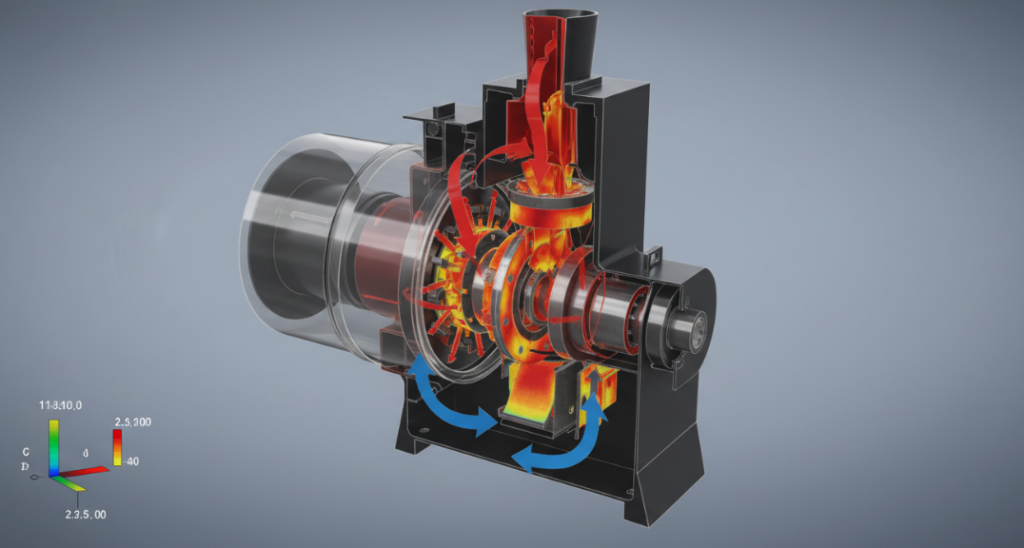
An air classifying mill (ACM) achieves continuous comminution and particle separation through a simultaneous interplay of mechanical impact milling and dynamic aerodynamic classification within a single chamber. The baseline air classifying mill principle relies on a high-speed rotor disk accelerating feed material against a stator liner to induce fracture, while an integrated variable-speed classification wheel utilizes counteracting centrifugal and aerodynamic drag forces to extract fine particles and reject oversized material back into the grinding zone. Your current particle size distribution (PSD) deviation is likely caused by undetected static pressure drops; leveraging the 2026 real-time feedback loops discussed below can tighten your D97 cut point tolerance by up to 12% without altering your existing hardware.
The Core Mechanics: Deconstructing the Impact-Classification Synergy
Understanding the precise air classifier mill working principle requires isolating the internal environment into two distinct thermodynamic and mechanical zones. Equipment evaluation experts trace machine efficiency directly to the transition phase between the lower grinding zone and the upper classification zone.
Rotor Dynamics and Attrition Mechanics
Impact velocity dictates the initial particle fracture rate. Feed material enters the mill mechanically or pneumatically and drops onto the rotating grinding disk. The rotor pins or hammers, spinning at tip speeds ranging from 90 to 120 m/s, subject the particles to extreme kinetic energy. Collision against the corrugated stationary liner causes immediate comminution through impact and attrition. The primary airflow, drawn from below the rotor, instantly sweeps the fractured particles upward toward the separator wheel. High-volume airflow prevents thermal degradation of heat-sensitive materials by carrying away the heat generated during the mechanical impact.
The Classification Zone: Aerodynamic Drag vs. Centrifugal Force
Particle extraction depends entirely on the mass-to-drag ratio at the edge of the classification wheel. As the air-particle mixture approaches the spinning wheel, particles face two opposing physical forces. Aerodynamic drag force from the system’s draft fan pulls the particles toward the center of the wheel, while the centrifugal force generated by the wheel’s rotation pushes them outward. Fine particles possess lower mass, meaning the aerodynamic drag overcomes the centrifugal force, allowing them to pass through the wheel blades to the cyclone discharge. Coarse particles, possessing greater mass, are dominated by centrifugal force, hitting the deflector ring and falling back into the rotor path for further comminution.
The ACD Force Triangle Model for D97 Cut Point Mastery
Precise control over the top size (D97) is a mathematical function of three variables rather than a simple machine setting. We developed the ACD (Attrition, Centrifugal, Drag) Force Triangle Model to quantify the operational limits of any ACM setup.
- Attrition (A): Controlled by rotor tip speed. Increasing rotor speed shrinks the median particle size (D50) but does not strictly govern the top size limit.
- Centrifugal (C): Controlled by the classifier wheel RPM. Higher wheel speeds generate stronger rejection forces, resulting in a finer D97 cut point.
- Drag (D): Controlled by the total air volume (CFM). Higher air volumes pull larger particles through the wheel, resulting in a coarser output.
Process engineers establish an optimal cut point by locking the total air volume (D) to maintain pneumatic conveying velocity, then fine-tuning the classifier RPM (C) against the rotor speed (A) to achieve the target PSD graph.
Table: Calcium Carbonate (CaCO3CaCO3) Particle Size (D50 & D97) Test Data at Various RPM/CFM Combinations
Material: Ground Calcium Carbonate (GCC) | Mill Type: Air Classifying Mill (ACM)
| Test ID | Classifier Speed (RPM) | Airflow Volume (CFM) | D50 (μmμm) | D97 (μmμm) | Particle Size Trend |
| Test 1 | 2,000 | 150 | 12.5 | 35.0 | Coarse |
| Test 2 | 3,000 | 150 | 8.2 | 22.5 | Medium |
| Test 3 | 4,000 | 150 | 5.8 | 15.0 | Fine |
| Test 4 | 5,000 | 150 | 4.1 | 10.5 | Ultra-Fine |
| Test 5 | 2,000 | 200 | 15.0 | 42.0 | Coarse |
| Test 6 | 3,000 | 200 | 10.5 | 28.0 | Medium |
| Test 7 | 4,000 | 200 | 7.5 | 19.5 | Fine |
| Test 8 | 5,000 | 200 | 5.2 | 13.5 | Ultra-Fine |
2026 Production Benchmarks: Real-Time PSD Integration
Static process control is rapidly becoming obsolete in high-yield powder manufacturing. The 2026 baseline for plant technical directors involves integrating inline laser diffraction sensors directly into the pneumatic conveying line downstream of the mill. These sensors transmit continuous PSD data at sub-second intervals to the mill’s PLC. When the sensor detects a fractional shift in the D97 limit, the PLC instantly adjusts the classifier wheel’s frequency inverter. This closed-loop integration eliminates the standard 30-minute lag of laboratory sampling, preventing tons of off-spec product and reducing specific energy consumption by up to 8.5%.
Engineering Pitfalls: Shroud Ring Build-up and “Ghost Particles”
Unexplained coarse particles appearing in your finished product usually originate from fluid dynamic anomalies rather than mechanical failure. Many senior operators misdiagnose this issue as classifier blade wear. The actual culprit is often the “Coanda effect” occurring on the shroud ring just below the classification wheel. Cohesive materials build up on this stationary ring over time, altering the aerodynamic profile of the airflow entering the wheel. This disrupted air channel creates localized velocity spikes, physically forcing large, unclassified “ghost particles” through the gaps and into the final product stream. Regular inspection of the shroud clearance and applying polished or Teflon-coated rings eliminate this boundary layer disruption.
Related “People Also Ask” (FAQ)
Technical FAQs for Process Engineers
What governs the maximum feed rate in an air classifying mill?
The specific heat load and the pneumatic conveying capacity of the system fan govern the feed rate limits. Overfeeding floods the grinding chamber, dropping the internal air velocity below the suspension threshold, which leads to motor amperage spikes and immediate mill stalling.
How does internal temperature affect the air classifying mill working principle?
Air density drops as the internal temperature rises due to mechanical friction. Lower air density reduces the aerodynamic drag force (the pulling force). To compensate for this thermal shift and maintain a consistent cut point, operators must proportionally reduce the classifier wheel speed.
Why is my D50 shifting even when classifier wheel speeds remain constant?
Variations in the raw material’s initial hardness or moisture content directly alter the fracture rate in the impact zone. If the rotor produces fewer fines due to harder feed material, the classifier wheel has less fine material to extract, fundamentally shifting the entire PSD curve outward.
Can an air classifier mill handle abrasive materials like silica?
Standard carbon steel or 304SS pins and liners degrade rapidly under abrasive impact. Processing materials above 4 on the Mohs hardness scale requires outfitting the rotor and stationary liner with tungsten carbide or ceramic aluminum oxide inserts to prevent rapid mechanical wear and product contamination.
What is the standard pressure drop across the classification wheel?
A well-optimized ACM operates with a pressure drop of 15 to 25 inches of water column across the mill body. Spikes beyond 30 inches indicate filter blinding in the downstream dust collector or a severe material choke within the grinding chamber.