 Клирик






Поиск
To thoroughly troubleshoot a vertical roller mill, you must examine the vertical roller mill gearbox and the vertical roller mill hydraulic system in conjunction. Hydraulic abnormalities are the primary cause of the sudden failure and scrapping of reducer thrust bearings. Once a hydraulic accumulator ruptures, the grinding roller becomes a rigid iron hammer, and 100% of the mechanical impact force is transmitted directly through the main shaft to the reducer, potentially shattering the gears within hours.
Stop disassembling these two modules for repair. You might be wasting a lot of time replacing the proportional valve, when the real root cause is excessive gear backlash; or you could be preparing to completely disassemble the reducer, only to find that the nitrogen‑filled bladder simply failed under load. This guide focuses solely on real-world, on-site troubleshooting, providing you with the diagnostic logic that truly enables rapid restoration of heavy‑equipment operations.
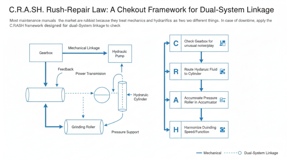
Most maintenance manuals on the market are rubbish because they treat mechanics and hydraulics as two different things. In case of downtime, directly apply the C.R.A.S.H. framework designed for dual-system linkage to check.
If the hydraulic cylinder is not synchronized, the pull rod force will be out of balance, which will instantly lead to the deflection of the reducer output flange.
Compare the vibration frequency of the vertical roller mill gearbox with the pulse frequency of the hydraulic pump. If the peaks coincide, it indicates that cross-resonance (Cross-System Chatter) is occurring between the systems.
don’t just look at the static pressure gauge, to measure the dynamic response time of the nitrogen bladder.
Focus on the hysteresis difference (hysteresis) between the electrical command and the actual displacement of the spool.
The local hot spots on the lubricating oil station or hydraulic oil tank often directly expose the location of the internal system string oil pressure relief.
In cement and slag mills, the 1 stop of the reducer often means the longest downtime of the month. If you are still waiting for the vibration switch to give an alarm before shutting down, then just wait for the overhaul and replacement.
Thrust tile micro pitting: destroy the invisible killer reducer
60% of the overhaul is due to the thrust bearing dry waste. The root cause is rarely the quality of the babbits, but the continuous small impact of the breakdown of the hydrodynamic oil film. When the vertical roller mill hydraulic system cannot buffer the fluctuation of the material bed, the thrust tile eats up all the kinetic energy.
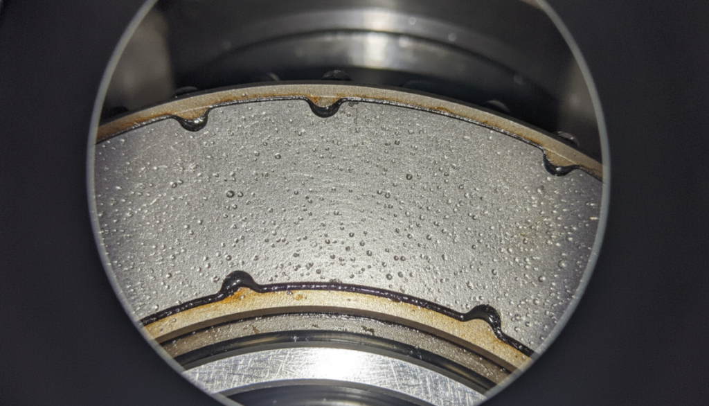
Before removing the main box body, probe into the thrust pad with an industrial endoscope. Look for dark spots like white frost on the metal surface. If you see micro-pitting corrosion, immediately take oil samples and check whether the iron and copper particles exceed 50 ppm. How to remedy it quickly? Directly increase the lubricating oil flow of ISO VG 320 to the thrust pad area by 15%, and at the same time keep an eye on the lubricating oil cooler. The oil supply temperature must be hard pressed below 45°C.
As long as the 2X frequency (double frequency) vibration value suddenly soars, go directly to check the bevel gear misalignment. The huge torque output by the motor and the drastic change in the depth of the material bed will abruptly push the input shaft out of the axial centering position.
Don’t expect to add or subtract gaskets just by static tooth contact spots. That thing is not allowed at all after loading. The actual backlash is measured 3 different positions at 120 degrees of the gear circumference by the lead wire pressing method. For a standard 3000kW vertical mill reducer, the backlash must be controlled between 0.8mm and 1.2mm. As long as the data is not in this window, immediately adjust the eccentric bearing sleeve, don’t hesitate.
Vertical Roller Mill Hydraulic System Emergency Repair: Restoring the Dead Angle of Grinding Pressure
The hydraulic system directly determines the efficiency of the mill. The pressure 1 falls or jumps, and the output is directly zero.
Once the hydraulic oil is dirty, the proportional reversing valve will be stuck, and the action of the grinding roller will be half a beat as slowly as when drunk. The central control room usually complains that the actual grinding pressure is always several seconds slower than the set value.
| Fault Code | Fault Description / Cause | LVDT Voltage Fluctuation | Hysteresis / Delay Time | Observable Symptoms |
| HYD-000 | Normal Operation (Clean Oil) | < ±0.05 V | < 0.2 s | Prompt response; Actual grinding pressure matches the set value synchronously. |
| HYD-102 | Mild Oil Contamination | ±0.1 V to ±0.3 V | 0.5 s – 1.5 s | Slight lag in grinding roller action; Minor pressure tracking error. |
| HYD-104 | Proportional Valve Spool Jam | ±0.5 V to ±1.5 V (Erratic) | 2.0 s – 5.0 s | “Drunk” or sluggish roller action; Central control room reports severe pressure delay. |
| HYD-201 | LVDT Core Mechanical Wear | Continuous Slow Drift | > 3.0 s | Unstable grinding pressure; System performs continuous but delayed corrections. |
| HYD-305 | Proportional Solenoid Weakness | Output drops by 10-15% | 1.0 s – 2.5 s | Gradual slowing of roller response time during continuous operation. |
| HYD-404 | LVDT Signal Loss / Cable Break | 0 V or > 10 V (Out of range) | N/A | Complete loss of closed-loop control; System interlock triggered (Emergency Stop). |
Regardless of the PLC, the proportional valve is directly driven by a 4-20mA signal generator. Keep an eye on the voltage feedback from the LVDT sensor. If the voltage value is jumping, rather than rising smoothly, the paint film or sludge has stuck the valve core. Unplug the valve, flush the valve block thoroughly with a special cleaning agent, and immediately upgrade the system’s external circulation (Kidney-loop) filtration accuracy to an absolute 3 microns.
On-site hydraulic engineers are most likely to fall into the pit of “false inflation. They glanced at the hydraulic gauge showing 120 bar and took it for granted that there was nothing wrong with the accumulator.
The fact is that once the skin bag is broken, high-pressure hydraulic oil will flow back into the intake chamber. The pressure gauge still shows the system pressure, but the elastic buffering effect of the gas has been zeroed, and the entire hydraulic station has become a rigid iron lump. How to check? Do a quick pressure relief test. Stop the hydraulic pump and open the drain valve. If the system pressure drops from 120 bar to 0 within 2 seconds, your nitrogen airbag has already been filled with oil. Quickly change the skin bag, and then re-charge it with dry nitrogen to 60% of the maximum working pressure (not a single point).
Just reading the theory manual will only make you fool around. We landed the C.R.A.S.H. Law at a large clinker mill suffering from repeated planetary gear damage.
The factory broke the sun wheel three times in two years. We attached the high-frequency sensor to the hydraulic rod and reducer box of the vertical roller mill hydraulic system synchronously, and caught a fatal hidden danger. At a grinding pressure of 85 bar, a slightly jammed relief valve initiated a hydraulic pulsation of 15Hz. Coincidentally, the 15Hz just hit the natural resonance frequency of the second-stage planetary gear of the reducer. The solution is extremely simple: we replaced the standard relief valve with an extremely fast response cartridge damping valve, and the hydraulic pulsation disappeared instantly. In the past 28 months, there has been no abnormality in the reducer of this factory.
The optimal temperature of the oil pool must be stuck between 50°C and 60°C. As long as it exceeds 70°C, the viscosity of the gear oil will fall through the safe hydrodynamic lubrication bottom line, and the gear bite surface will immediately have hard metal friction.
Intermittent pressure drop is basically due to oil flow inside the hydraulic cylinder seal, or the main system overflow valve is about to be scrapped. Take an infrared temperature measuring gun to scan the surface of the cylinder barrel for local heat. Internal leakage and friction will produce very obvious high temperature points.
According to the operating load of the equipment, the nitrogen pre-charge pressure must be measured once every 3 to 6 months. As long as the pressure drops by more than 10%, the bladder is breathable or the inflation valve is leaking. The air must be replenished immediately, otherwise the grinding roller will completely lose its cushion when it jumps on the material bed.
Absolutely can. Without the hydraulic buffer 1, the grinding roller becomes a hammer weighing several tons. Every time the material on the grinding disc jumps, the devastating shock wave will be directly smashed into the thrust tile of the reducer along the main shaft, and the service life will fall off a cliff.
Vibration of the input shaft is usually the cause of these 3: wear of the elastic coupling, misalignment of the motor and reducer, or pitting of the 1 stage bevel gear pinion. Don’t rush to open the observation hole of the reducer, first make a motor laser alignment, and then see if the elastic block in the coupling has been cut to pieces.