 Клирик






Поиск
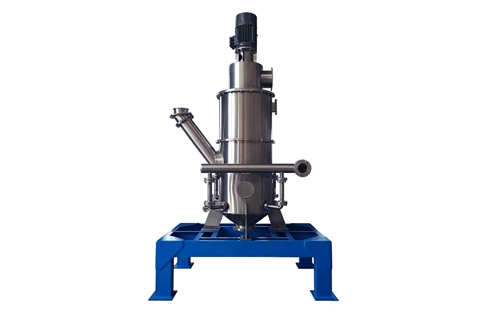
As the name suggests, an air classifier mill is not simply an independent airflow classifier. Its core advantage lies in the clever integration of fine crushing and dynamic airflow classification into a single device. This device generally includes an impact crushing unit, a dynamic airflow classifier, and an airflow conveying and collection system. The industry sometimes uses ‘grading mill’ to refer to this type of crushing equipment with its own airflow classification function. However, it should be noted that if only ‘independent airflow classifier’ is mentioned, it usually refers only to an external classification component.
Materials typically enter the crushing zone through metered feeding or pneumatic conveying. At this time, the impact member on the rotor runs at high speed, causing the material to collide violently with the impact member, liner or gear ring, thereby achieving continuous refinement of particle size. Immediately afterwards, the crushed material will be carried into the grading zone along with the airflow. Here, the centrifugal force generated by the high-speed rotation of the grading wheel, coupled with the traction force of the airflow, together influence the motion trajectory of the particles. The fine powder that meets the standards will pass through the grading wheel smoothly and become the final product; while the coarse particles that are too large will be ‘rejected’ and fall back to the crushing area for further processing ‘re-furnace reconstruction’.
To control the particle size separation, cycle load or particle size distribution of the finished product, you need to keep a close eye on a number of parameters: the speed of the grading wheel, the processing air volume, the speed of the crushing rotor, the feeding rate, and even the density of the material itself and the initial particle size distribution will also have an impact. This not only affects the quality of the finished product, but also directly affects the system temperature rise and energy consumption. For example, increasing the air volume can indeed improve the delivery effect and help cool the system, but this will also change the flow field inside the grading zone and make the load on the fan and filter heavier. Therefore, it is meaningless to discuss a specific speed or air volume value on the equipment panel separately, without considering the specific material characteristics and actual working conditions.
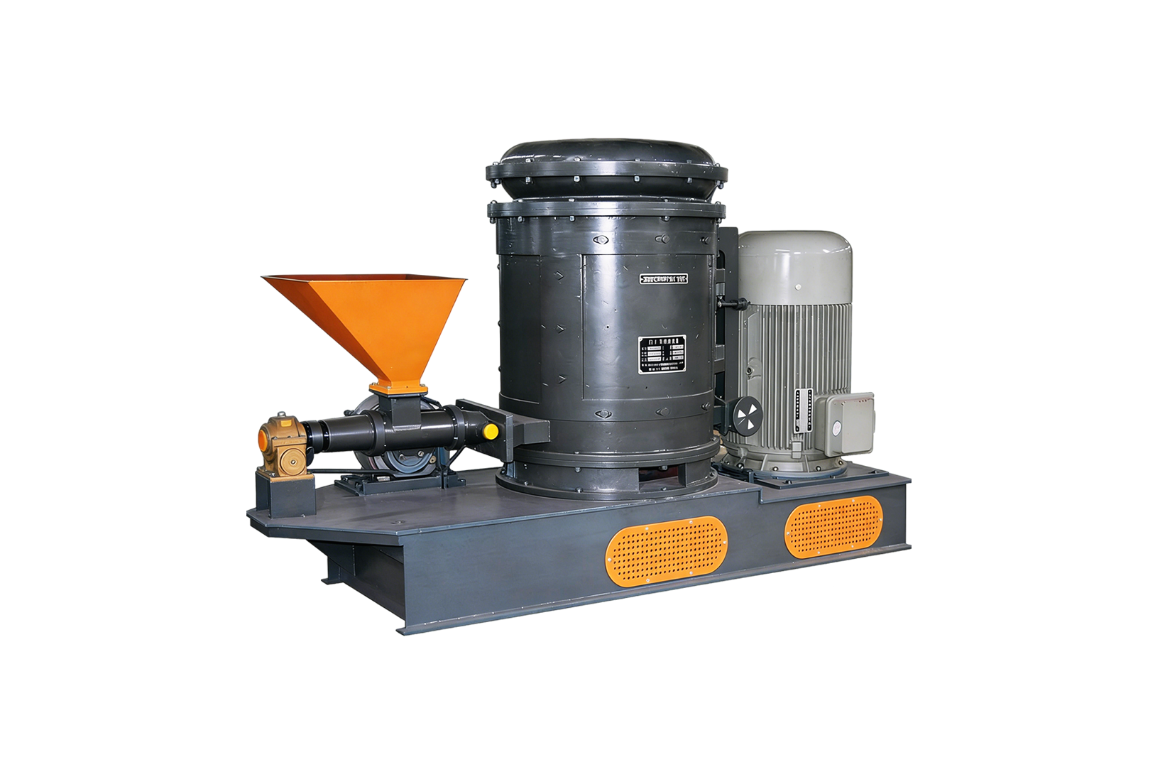
A standard air grading mill main unit typically consists of a feed inlet, a crushing rotor, an impact member, a liner (or ring gear), a grading wheel, a guide component, an airflow channel, a drive motor, a fine powder outlet, a coarse powder return channel, and an access door. However, if you broaden your focus to the entire system, you will also see supporting facilities such as metering feeders, fans, pipes, cyclone separators (or bag dust collectors), shut-off fans, metal separators, control systems, and dust removal devices.
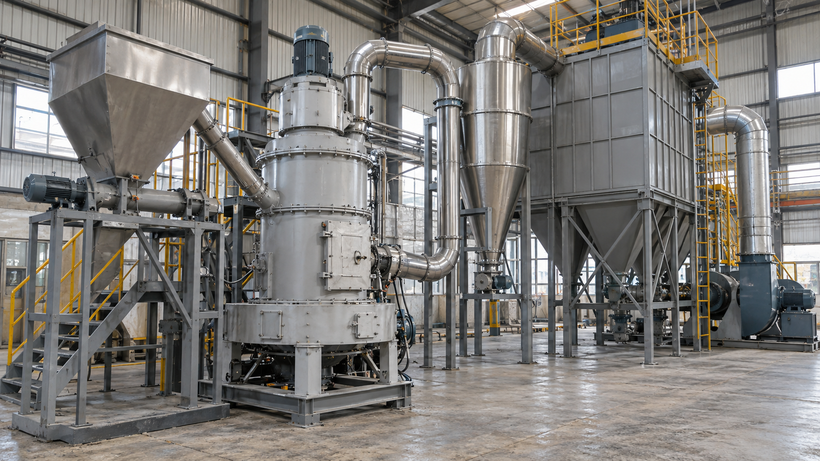
This equipment can both walk away from the road and operate as a closed-circuit system. In closed-circuit operation, the finished product leaves the main unit along with the airflow and is finally collected into the bag by the cyclone separator or filter; while the coarse powder will circulate inside or outside the equipment to continue the crushing task. Here, the fan, conveying, and collection processes all fall within the boundaries of the entire system. Therefore, a qualified structural schematic diagram must at least clearly mark the feeding, crushing, grading, coarse powder return, fine powder collection and airflow direction. Just taking a diagram of the main machine’s appearance cannot explain the internal doorways and overall configuration.
A simple air flow classifier mainly does the work of ‘selecting size’ (particle size separation). It often has to be combined with crushing equipment such as ball mills, roller mills or hammer mills to form a closed-circuit system. The air classification mill combines crushing and classification ‘into one’. In addition, the word ‘mill’ is in the name, which does not mean that the crushing structure of all equipment is the same.
For example, air jet mills (Air Jet Mills) mainly rely on high-speed air flow to push particles to collide with each other to crush them. There are often no mechanical crushing tools embedded in them; but air staged mills mainly rely on mechanical impact parts ‘hard-on-hard’. The two are completely different in terms of crushing mechanism, wear source, temperature rise performance and energy consumption structure. We must not confuse these two types of equipment just because everyone ultimately produces fine powder.
Before making a decision on the type, it is necessary to first understand the various characteristics of the material: composition, hardness, abrasiveness, moisture, viscosity, thermal sensitivity, flammability, and feed particle size. At the same time, you also need to clarify your production requirements: what is the production capacity? d50/d97 or at which value is the maximum granularity stuck? How many coarse particles are allowed to mix in? What is the span of the particle size distribution? What is the temperature rise limit? What are the requirements for product purity? Are there any pollution restrictions? Is it continuous production or intermittent work?
There are two core tasks that must be distinguished here: first, to crush the material to a specific fineness ‘smash’, which tests the crushing strength of the equipment; second, to remove coarse particles of a specific size, which places more emphasis on the cooperation of the grading wheel, the processing air volume and the closed-circuit return flow. Although the data used in the final analysis of these two matters were granular indicators, their focuses on equipment configuration and verification were quite different.
In addition, the focus of the configuration must follow the material characteristics. If the particle size distribution requirement is narrow, or the cutting point needs to be adjusted online, then the focus must be on comparing the style of the grading wheel, independent drive design, speed control method, air volume control and coarse powder return structure; when encountering highly abrasive materials, the wear-resistant materials of the impact parts, linings, grading wheels, fans and collection parts must be strictly checked and whether they can be replaced; for heat-sensitive materials, it is necessary to ensure sufficient cooling airflow, strictly control temperature rise and confirm the conditions for continuous operation; if the production line changes materials frequently, it is necessary to check whether the equipment structure is clean, whether there are easily disassembled parts, sanitary dead corners, sealing, and whether the cleaning verification has been passed. If it is a flammable, explosive or toxic powder, safety designs such as anti-static grounding, access control interlocking, anti-pressure explosion protection, explosion discharge and suppression system, inert gas protection and filter isolation must all be arranged.
A qualified technical specification must at least specify the model, dimensions of the crushing rotor and grading wheel, forms of impact elements and liners, feed particle size, finished product size requirements, throughput, power of the crushing and grading motors, processing air volume, speed range, material moisture requirements, wear-resistant and contact-material grades, dust collection method, and overall system configuration. The engineering drawings should also clearly specify the external interface relationships, the directions of material inlets and outlets, the locations of pipe nozzles, inspection doors, foundation drawings, as well as the layout of fans, collection equipment, and the control system.
When it comes to granularity metrics, never be vague. Is it d10, d50, d90, d97, the maximum particle size, or the sieve residue? Without a clearly defined testing method and standardized conversion criteria, terms such as ‘microns,’ ‘mesh size,’ or ‘ultrafine powder’ should never be used interchangeably. Similarly, the production capacity, air volume and motor power must also be bound to the specific equipment type, material type, target fineness, moisture, feed particle size and test conditions. Generally speaking, the finer the target granularity, the greater the system cycle load may be, or the throughput may drop directly. However, the exact change depends on the material, equipment structure and process conditions, and it is impossible to apply a fixed proportion to blind estimation. Therefore, when releasing the particle size data, it is best to record the sampling status, dispersion method, test instrument, specific means, index definition and test environment of the samples.
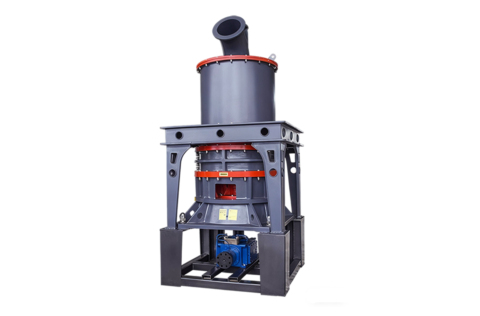
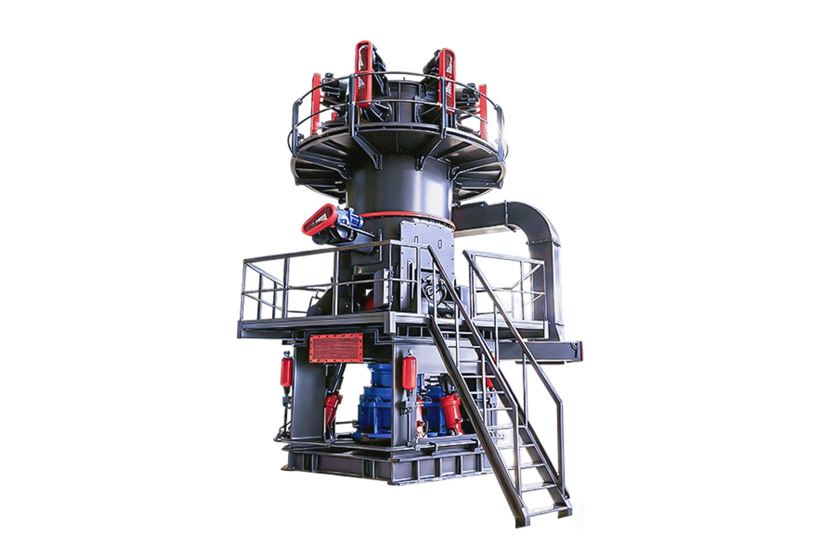
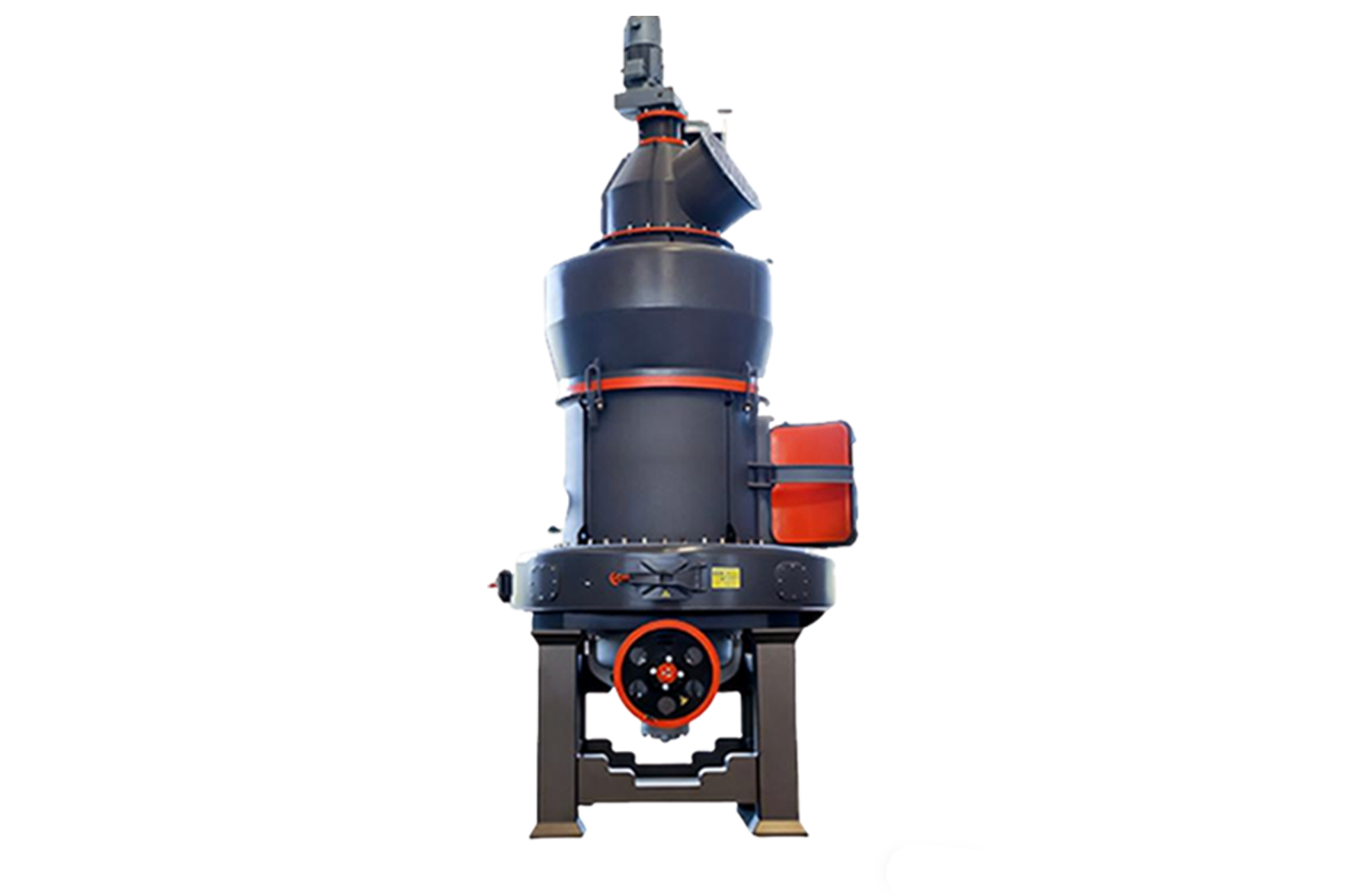
In Collyric’s product classification system, the full name of CLCM is ‘CLCM Vortex Air Classifying Mill’ (CLCM Vortex Air Grading Mill), and the common term is ‘Air Grading Mill’ (Air Classifier Mill). What can be confirmed here is only the correspondence between the specific model name and the common name of the equipment. As for CLCM’s real crushing particle size, capacity data, applicable raw materials, working conditions and detailed structural parameters, it is finally necessary to consult the applicable technical documents of the model and cannot be generalized without the documents.