 Clirik





Search
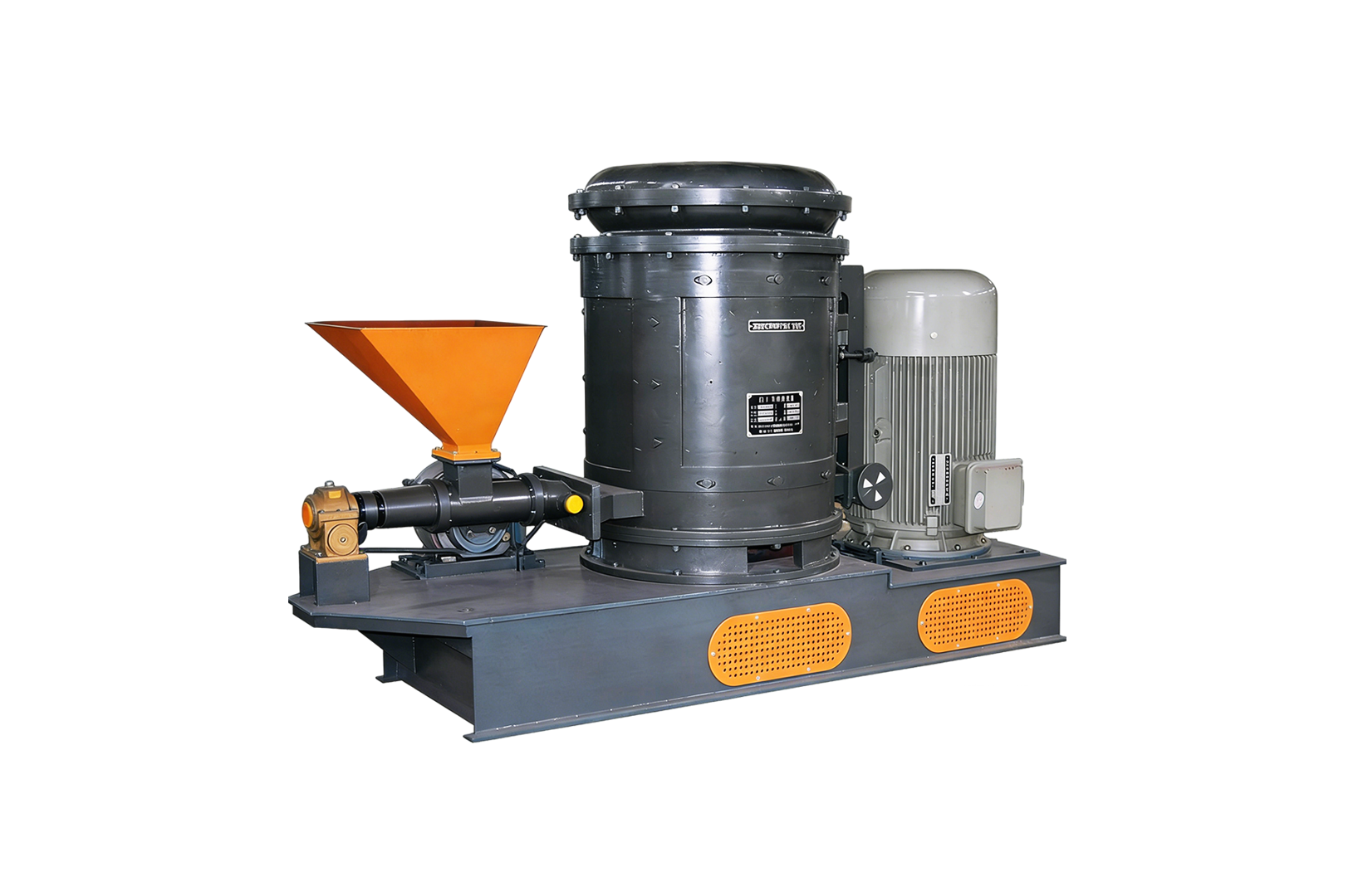
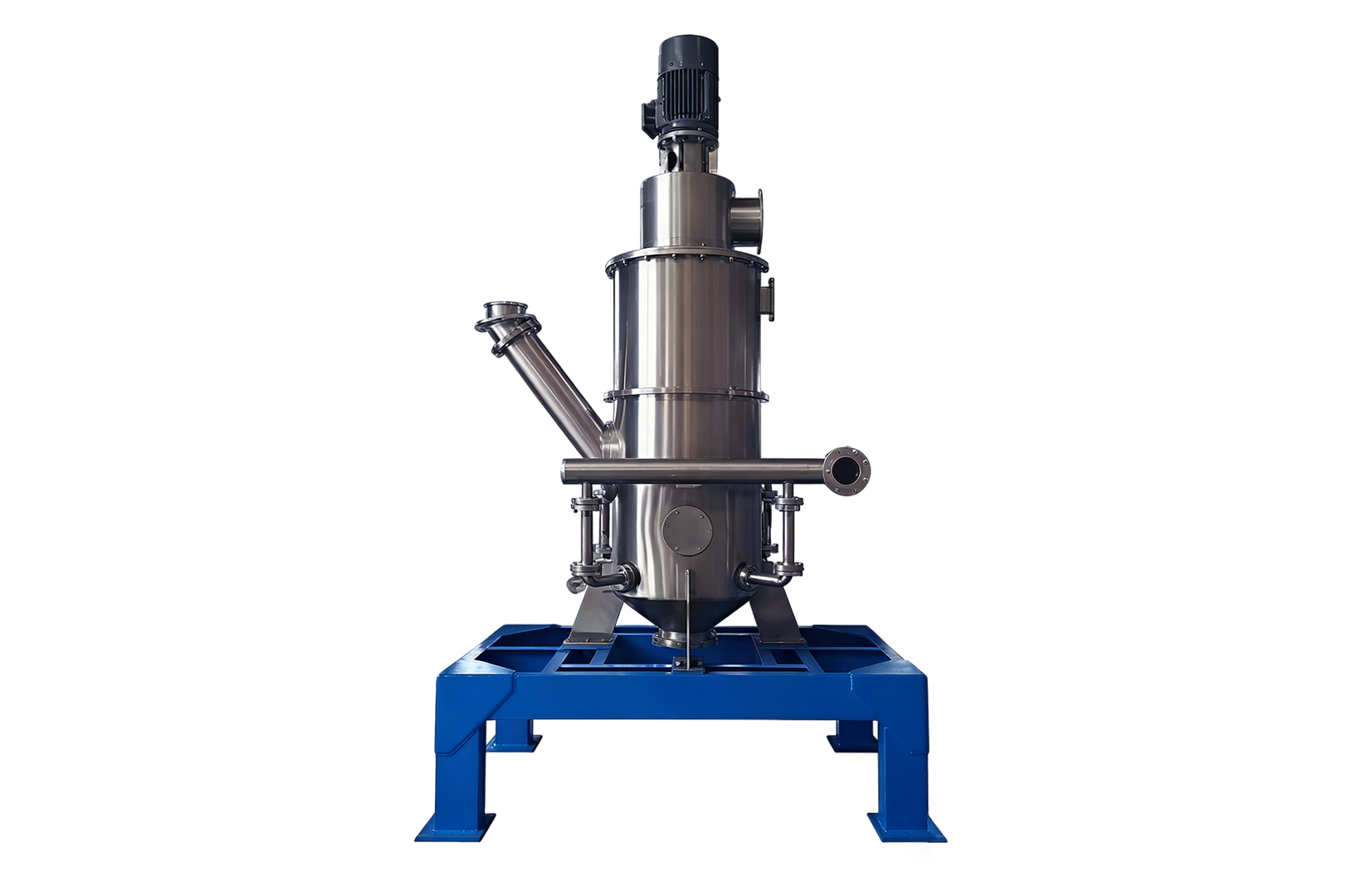
Air Classification Mill (Air Classifier Mill, referred to as ACM) is how to work? Simply put, it is the high-speed mechanical impact crushing and dynamic airflow classification of these two steps, hard into a closed chamber, so that they are at the same time. As soon as the raw material enters the crushing zone, the high-speed rotating hammers smash it into fine powder; at the same time, a secondary airflow inside the machine immediately lifts this fine powder upward, carrying it to the high-speed rotating classifier wheel. The grading wheel is like a strict security guard, which ruthlessly returns the particles that are too big to the crushing area for “recycling”, releasing only the fine powder that meets the standard size, allowing them to pass through and enter the collection system smoothly.
To truly understand the operating principles of an air‑classifying mill, merely examining its external mechanical structure is not enough; you must delve into the fluid‑dynamic interplay within the grinding chamber. Many operators on site are unable to achieve a stable particle size distribution (PSD); to put it plainly, they haven’t fully grasped the intricate interplay between air flow rate and rotor speed. Today, we will use the structural diagram of the air flow grading mill to strip the strong mechanical force inside to the bottom. By the way, we will point out a line of measured data, focusing on lightning protection, which is enough to destroy the whole batch of materials.
Any successful grinding operation is inseparable from the “P.A.C. mechanical iron triangle”: particle quality (Particle Mass), aerodynamic drag (Aerodynamic Drag) and centrifugal force (Centrifugal Force). After understanding this logic, you don’t have to rely on “guessing” to adjust the machine at the scene.
The most basic principle of air flow grading mill is that the real size differentiation occurs at the critical point where the two forces face to face. Those large and heavy coarse particles, because of their large mass and centrifugal force, occupied an absolute advantage, abruptly resisted aerodynamic resistance and were severely thrown back to the crushing area at the bottom. And those fine powders, because they are too light, centrifugal force can’t catch them at all, and aerodynamic resistance can easily take them through the blades of the grading wheel and enter the final finished product collector comfortably.
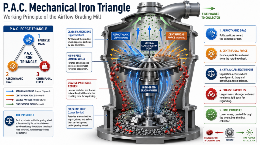
With a precise structural diagram, you’ll immediately understand why this device outperforms conventional pin mills or hammer mills. Its greatest advantage is that it eliminates the external material-handling stage between pulverization and classification.
The lower half of the cavity serves as the base for the main rotor. As soon as the material falls into this area, it immediately collides with crushing pins or hammers moving at a linear speed of 80 to 120 meters per second. This terrifying transfer of kinetic energy can instantly shatter solid materials into fine fragments. Moreover, the inner wall is fitted with a toothed stator liner, forcing the material to bounce back and forth at high speed between the rapidly rotating pins and the stationary inner wall until it is completely pulverized.
Directly above the crushing rotor hangs the dynamic classifier wheel (grading wheel). It is an independently driven squirrel-cage rotor. The upper limit of the final product’s particle size (D97) is entirely determined by the blade spacing and rotational speed of this impeller.
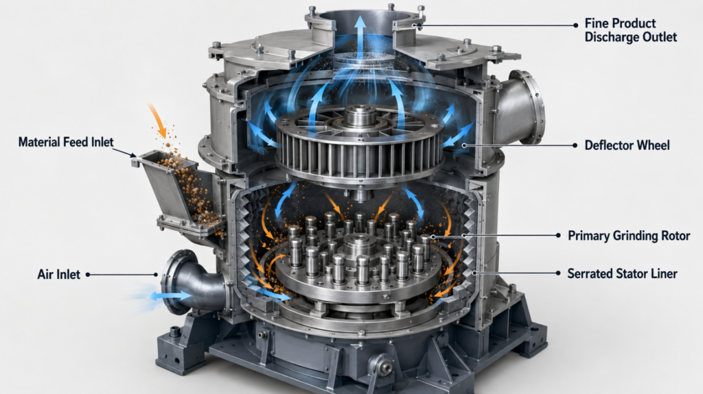
For process engineers, if they want to optimize machine parameters, they must have a clear mental image of this internal continuous-loop system. The entire air-classified grinding process operates in strict accordance with the three-step internal circulation.
The rotary feed valve delivers bulk material into the feed chute. Under the combined action of gravity and internal negative pressure, the material is drawn into the rotor zone. It starts with a series of violent impacts, completing the initial crushing.
Fresh air is drawn into the mill’s bottom casing. This upward airflow serves two purposes: first, it cools the crushing zone—absolutely vital for heat-sensitive materials, preventing them from melting due to high temperatures; second, it “blows” (fluidizes) the freshly crushed particles, carrying this entire cloud of fine dust straight up toward the classifier wheel at the top.
When the dust cloud collides with the high-speed rotating classifier wheel, the actual physical sorting process begins. As long as your rotational speed is set correctly, the grading mechanism ensures that absolutely no oversized coarse particles can slip through undetected. The coarse particles that were mercilessly rejected flow along the chamber wall and, under the influence of gravity, fall back into the crushing pins at the bottom. This closed-loop recirculation, performed entirely within the machine, eliminates the need for an external vibrating screen while ensuring a very narrow and tightly concentrated product particle size distribution.
Many inexperienced operators mistakenly assume that simply cranking up the classifier wheel’s speed will inevitably produce a finer powder. Field tests conducted by the industry have long since thoroughly refuted this notion.
When the rotational speed of the graduated wheel is pushed beyond its limit, a so‑called “overspeed illusion” arises. The extremely high linear velocity creates an air turbulence wall as solid as rock around the blades (the Coanda effect), blocking even the ultra-fine particles that should have qualified from entering. What was the outcome? The material became tightly trapped within the chamber, stuck in an endless grinding loop. This not only causes the mill’s internal temperature to soar and leads to thermal degradation of the product, but also results in an alarmingly rapid wear rate of the grinding pins.
We once conducted a control experiment using titanium dioxide (TiO2) to determine just how much damage this indiscriminate speed‑up would inflict on the actual yield.
| Classifier RPM | Expected D50 | Actual D50 Output | Chamber Temperature |
|---|---|---|---|
| 3,000 RPM | 15 µm | 15 µm | 40°C |
| 4,000 RPM | 10 µm | 10 µm | 45°C |
| 5,000 RPM | 7 µm | 9 µm | 65°C |
| 6,000 RPM | 5 µm | 12 µm — Agglomerated | 90°C — Warning |
Today, equipment manufacturers have long since abandoned the “blind men and the elephant”–style trial-and-error approach to machine design; they now all rely on computational fluid dynamics (CFD). In older ACM models, the “airflow dead zone” directly beneath the grading wheel was often a problem—when the wind speed dropped in that area, all the waste would pile up and get stuck there.
Even before the steel enters the foundry, engineers have already mapped out the airflow patterns inside the new model with CFD software. Even slightly adjusting the angle of the stator liner or fine-tuning the gap between the grinding rotor and the classifier wheel can maintain a perfect laminar upward airflow inside. This approach not only prevents easily agglomerating materials such as cocoa powder and slaked lime from forming clumps, but also slashes the energy consumption per ton of powder by a full 18%.
What exactly is the difference between an air classifier and an air‑classifying mill?
The air classifier is a purely dry sorting device that relies entirely on aerodynamic forces to separate a ready‑prepared powder into coarse and fine fractions. Meanwhile, the Air‑Classifying Mill (ACM) is a versatile all‑rounder: it not only features a mechanical rotor that crushes the material but also incorporates an internal classifier wheel that sorts the particles, enabling a single machine to handle both comminution and classification in one go.
How do you adjust the granularity of a finished product in ACM?
You have two key variables you can adjust: the rotational speed of the top-stage impeller and the overall exhaust airflow rate. Within the safe operating range, increasing the classifier wheel speed or reducing the total air flow will produce a finer powder.
Which materials are unsuitable for air-classified grinding?
That highly abrasive material—such as silicon carbide or quartz—will quickly wear down a high‑speed rotating pin if it’s exposed for even a short time. Additionally, materials that are extremely heat-sensitive or have a high fat content and are particularly sticky (unless subjected to liquid nitrogen cryogenic treatment) will melt upon exposure to heat, instantly clogging the classifier wheel.
Why does my air-classified grinder keep overheating?
Overheating boils down to a few common causes: either you’re feeding material too aggressively, overloading the machine; the cooling air drawn in is simply insufficient; or you’ve set the classifier wheel’s speed to an extreme setting, trapping the material inside the chamber in an endless loop—unable to escape—and literally overheating the machine.
What is the typical linear velocity of a crushing rotor?
The tip‑line velocity of the primary crushing rotor typically ranges from 80 to 120 meters per second; the exact setting depends on the hardness of the feed material and the amount of kinetic energy required to break it.