 Clirik





Search
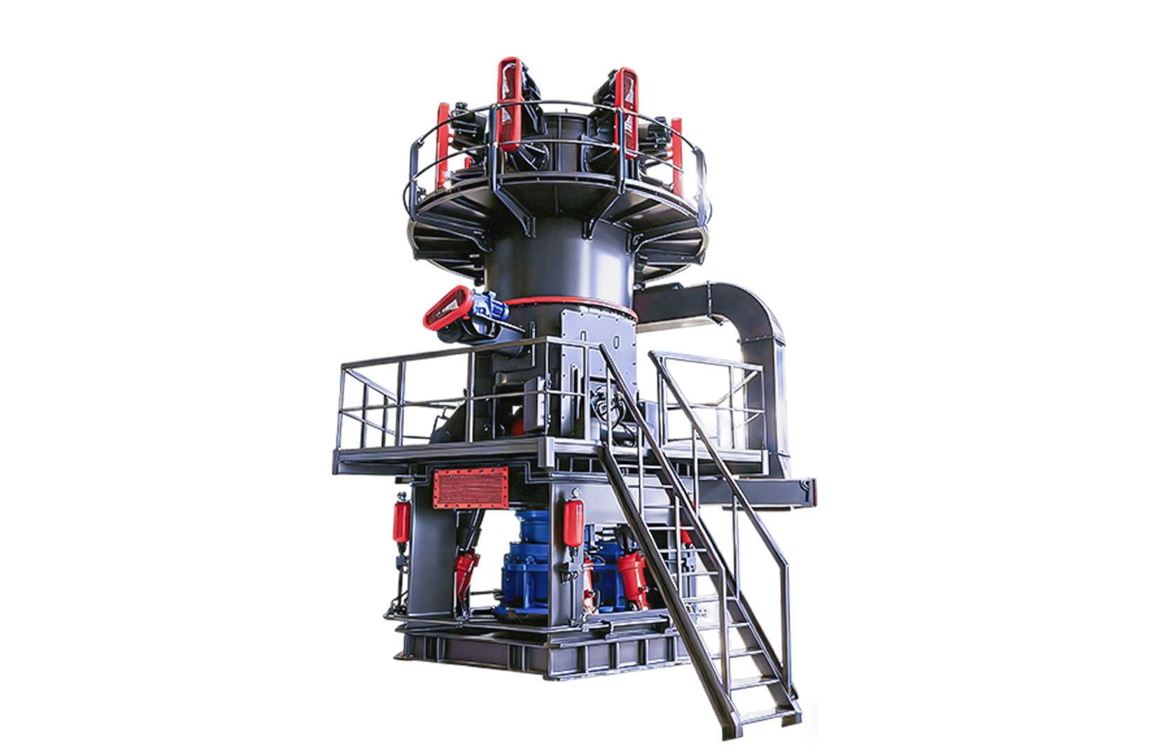
How does a vertical roller mill (VRM) grind materials? In simple terms, the material is clamped between hydraulically pressurized grinding rollers and a rotating horizontal grinding table. Mechanical compression, combined with upward‑flowing hot air, simultaneously accomplishes crushing, drying, and classification in a single pass. When examining the structural diagram of a vertical roller mill, you should focus on five key components: the rotating grinding table, the independent roller assembly, the dynamic rotary classifier, the air ring, and the hydraulic‑pneumatic pressurization system. Many novice operators, as soon as they encounter a drop in output, fixate solely on the pressure of the hydraulic system. This is utterly wrong, because they have completely overlooked the invisible aerodynamic equilibrium within the mill casing. Today, we’ll break down in detail how these physical‑mechanical components and the internal airflow work together. At the end of this article, we’ve also included vibration‑mitigation field‑testing data—exclusively compiled by our front‑line engineers.
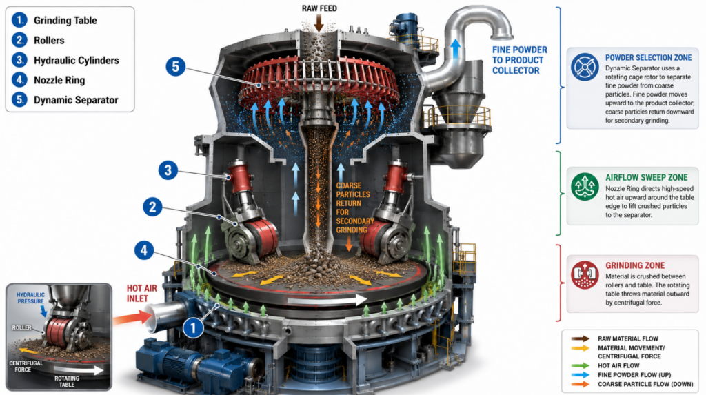
The internal structure of the vertical mill is actually a continuous circulation system, which can be roughly divided into three working areas: grinding area, airflow cleaning area and powder selection area.
The grinding disc is the power of the whole system. It rotates at a constant speed to generate centrifugal force, throwing the raw material falling in evenly to the edge of the disc surface. As for the grinding rollers, they are suspended by heavy hydraulic cylinders and do not directly hit the metal grinding disc. The grinding roller is pressed on the upper surface of the material bed to roll, and the downward pulling force of the hydraulic system is solidly converted into huge shear force and extrusion force on the material.
The function of the air spray ring is to guide the high-speed hot air flow to accurately blow up along the edge of the grinding disc. This angled air flow can instantly “catch” the crushed material spilling from the edge of the mill. If the angle of the air spray ring is not aligned or the wear is serious, the material will fall directly, causing a large number of heavy coarse particles to fall into the mill base, directly clamping the scraper to overload.
The dynamic separator installed at the top determines the thickness (fineness) of the final product. Its rotating cage rotor creates a controlled vortex. Qualified fine powder can smoothly pass through the rotating rotor blades and be taken away by the wind into the finished product collector (bag filter); However, when the unqualified coarse particles hit the steel blades, they will lose their kinetic energy and fall back to the grinding disc along the central return chute for secondary grinding.
If you want to really play with the vertical mill, the operator must have a thorough understanding of the iron triangle of “T-A-S (grinding disc-air flow-powder separator). If you move any one of these parts, the other two will inevitably have a physical chain reaction.
ShiPing ChaRu (Please insert a 3D animation video showing the material flow, starting from the feed chute, moving under the rollers, getting lifted by the air, and sorted by the separator.)
In order to run smoothly, the thickness of the material bed must be stable. Taking standard cement clinker as an example, the thickness must generally be controlled at 30 to 50mm. The raw material falls to the center of the rotating mill and is thrown out by centrifugal force until it is stopped by the retaining ring at the edge. If the feeding amount is given too much, the material bed will suddenly become thicker and the grinding roller will be pushed up. This mechanical jump is extremely dangerous, will cause the mill violent vibration, and finally force the system automatic trip shutdown.
The hydraulic accumulator will accurately exert its power to crush the grinding roller on a stable material bed. There is a key component here-the nitrogen bladder in the accumulator, which acts as a “shock absorber. Without these nitrogen bladders as buffers, the hard hydraulic rigidity can shatter the roller bearing in a few hours when encountering particularly hard coal or limestone.
The flow of hot air surges into the mill base at a speed of more than 40 meters per second. This strong air current lifts up the crushed mixed material. Those large pieces of material that were too heavy and not crushed fell back through the air spray ring and became “spitting slag”. The dust suspended in the air flies all the way to the powder separator. If you increase the speed of the classifier, the large particles will not be able to get out, which will directly cause the cycle load inside the mill to soar.
The front-line engineers found at the scene that there were only a few mechanical failures over and over again, all because the operator did not understand the basic principles.
Many operators increase the pressure of the hydraulic system at every turn in order to match the hourly output. In fact, too much pressure will instead press the raw material bed into a hard and rigid “discus”. This will not only reduce the grinding efficiency, but also cause the main motor current overload trip.
The differential pressure reflects the direct resistance of the internal space of the mill to the airflow. Once the differential pressure rises, the powder backlog inside the mill is too much. At this time, the most effective way is to quickly reduce the amount of new material fed. If you try to speed up the exhaust fan speed to “blow out” the material, it will only make the internal airflow more chaotic and accelerate the wear of the spray ring.
The physical function of the retaining ring on the edge of the grinding disc is to “pocket” the material bed “. If the retaining ring is severely worn, the uncrushed material will slide out of the grinding disc too quickly. This is equivalent to directly pumping out the key material bed buffer layer, which will inevitably lead to catastrophic hard-hitting friction between the grinding roller and the metal lining plate of the grinding disc.
Our field test data collected at 3 dry-process cement plants show that the relationship between operating pressure and wear rate of abrasive rolls is not linear at all. Once you push the device past the optimal pressure threshold, the wear rate of the internal parts will increase exponentially.
| Hydraulic Pressure Setting (bar) | Average Output (t/h) | Power Consumption (kWh/t) | Roller Wear Rate (mm/1000 h) |
|---|---|---|---|
| 90 | 72 | 10.8 | 0.32 |
| 110 | 81 | 10.1 | 0.39 |
| 130 | 88 | 9.8 | 0.50 |
| 150 | 91 | 10.6 | 0.70 |
What is the difference between vertical mill (vertical mill) and ball mill?
Vertical mill is an all-in-one machine, which puts grinding, drying and dynamic powder selection into a compact equipment. Compared with traditional ball mill, its unit energy consumption is 30% to 40% lower. The ball mill smashes the material by the random impact force of the steel balls falling from the rotating cylinder, while the vertical mill relies on extremely accurate hydraulic squeezing force.
Why do vertical mills sometimes vibrate so much?
The root cause of the vibration is directly on the instability of the material bed under the grinding roller. The specific reasons are usually that the raw material fed in is too dry, the tension of the hydraulic nitrogen airbag is incorrect, or the retaining ring is worn too much, resulting in the material bed with normal thickness not being paved at all.
How does the hydraulic system in the mill work?
The hydraulic cylinder will produce a downward pulling force, the grinding roller dead pressure on the rotating material bed. The nitrogen-charged accumulator connected with these cylinders acts as a heavy shock absorber, allowing the grinding roller to maintain pressure when rolling materials of different hardness without breaking the mechanical connection.
What is the main function of the jet ring in the vertical mill?
The air spray ring is equivalent to a pneumatic directional valve. It accelerates and blows up the high-temperature gas entering the system, accurately capturing the materials that have just been crushed and thrown out of the mill, and forcibly preventing them from falling into the bottom mechanical base.
Vertical mill is how to control the fineness of finished products?
The operator only needs to adjust the speed of the top dynamic separator. The faster the rotor of the powder separator turns, the greater the centrifugal force generated, and the easier it is for large particles to be “beaten” back and fall back to the grinding disc along the chute to grind again.