 كليريك




بحث
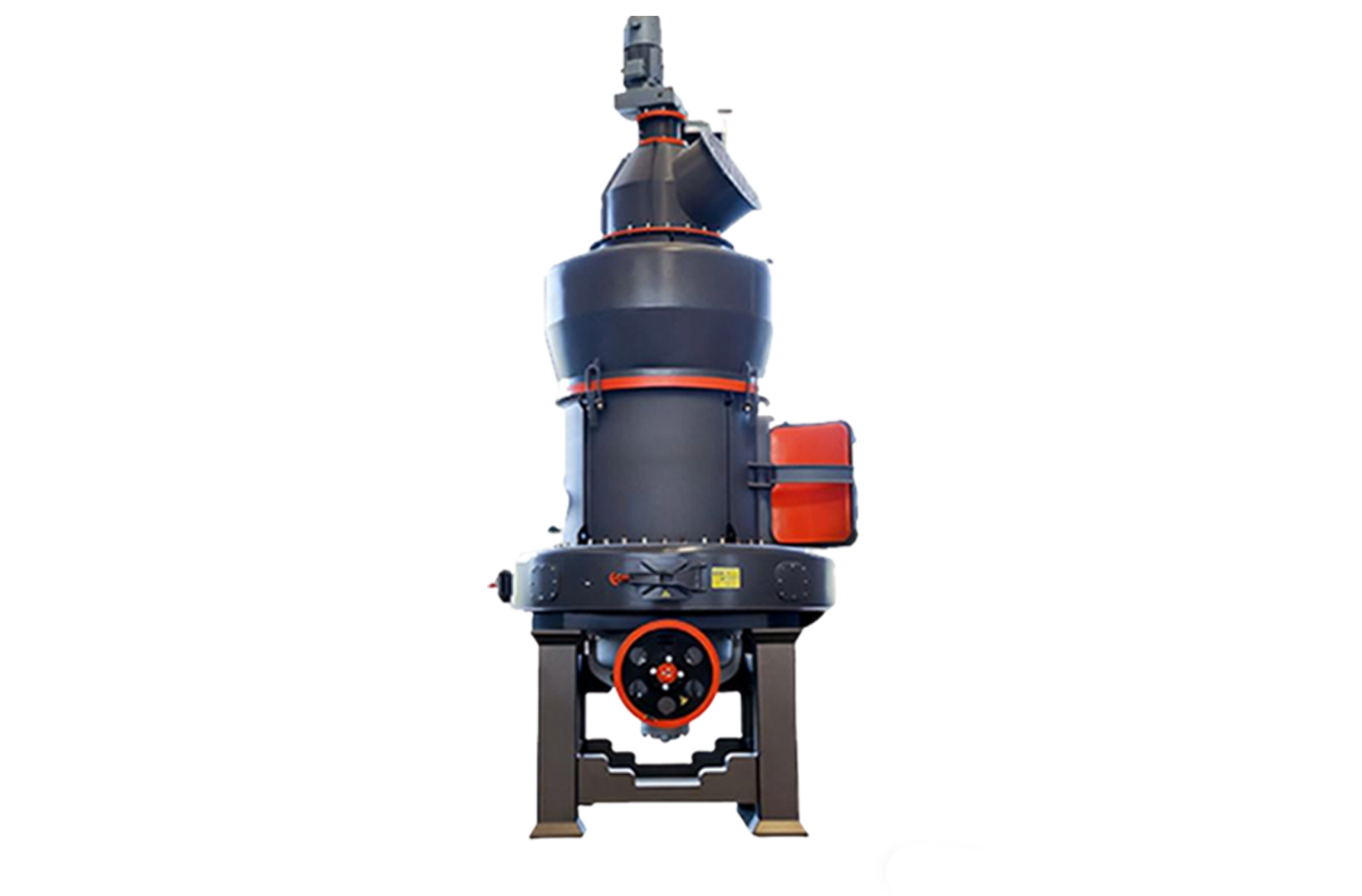
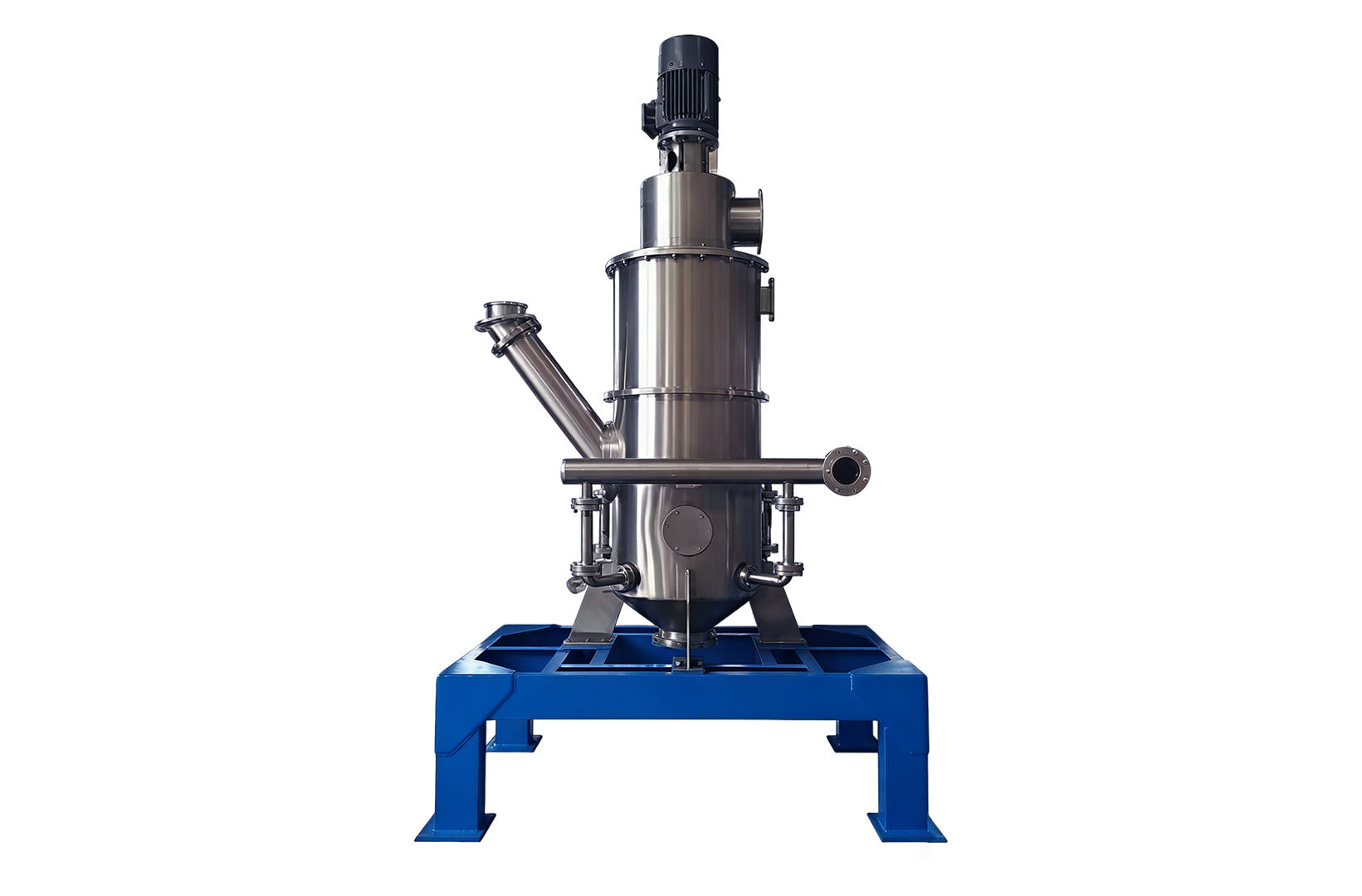
There is an unusual noise in the area around the Raymond mill reduction gearbox. First, see if it changes with the feeding. For Raymond mills equipped with a main drive reduction gearbox, the load generated when the grinding rollers crush the material will be transmitted back to the reduction gearbox through the main shaft. If the abnormal noise only occurs when the feeding fluctuates, and the main motor current also fluctuates at the same time, check the feeding and grinding ends first. If the feeding is stable, the abnormal vibration of the box measuring point is still increasing, and the wear particles in the oil sample are also increasing, the gears and bearings in the box should be checked first. Clirik’s CLRM Raymond mill operating principle description shows the relationship between the spindle, mill roller frame, mill rollers and mill ring. How Clirik Raymond Mills Work · NASA Equipment Condition Monitoring Guide
First check the nameplate of the entire machine and the reduction gearbox, and then confirm the positions of the motor, transmission connection, reduction gearbox and mill spindle according to the final assembly diagram. Find the feed rate, speed, main motor current, and oil temperature at the time of the fault from the existing operating records. When comparing vibrations, try to use the same measuring point and direction under similar operating conditions. When it is necessary to remove the shield, inspect the coupling, or unbox the equipment, authorized personnel shall shut down the equipment according to on-site procedures, lock and label it, handle residual energy, and verify isolation. NASA Vibration Analysis and Field Inspection Guidelines · OSHA Hazardous Energy Control Standards
| What you observe | What to check first | What the findings tell you |
|---|---|---|
| Vibration near the mill main shaft rises with motor current as feed increases | Review the feed logs. After shutdown and isolation, check that the rollers turn as specified and inspect the plows and grinding ring for abnormal wear or material buildup. | If a grinding or feeding problem coincides with the symptoms, correct it and recheck gearbox vibration. |
| Vibration is strongest near the coupling, especially after the motor or gearbox was reinstalled | Check that the foundation bolts are secure and review the coupling alignment readings. | Correct any looseness or out-of-tolerance alignment. If vibration persists, compare gearbox readings with the oil analysis results. |
| Oil temperature rises and oil appears at a shaft exit or housing joint | Trace the leak. Check oil level, lubricant specification, and cooling system operation, if fitted, against the manual for that gearbox. | If the oil level has dropped, determine where the oil escaped and whether lubrication was affected. Rising wear debris also warrants an internal inspection. |
| Feed and speed are steady, but vibration at a gearbox measurement point and wear particles in the oil keep increasing | Verify the oil analysis trend and review the vibration spectrum at the affected measurement point. | If both indicators continue to worsen, plan an internal inspection. Retain an oil sample and any visible debris before cleaning the gearbox. |
The main motor current can help determine when the mill load changes. To further locate the fault inside the reduction gearbox, it is necessary to combine the location and frequency of vibration, the oil sample trend, and the necessary unboxing inspection. How Clirik Raymond Mills Work · NASA Equipment Condition Monitoring Guide · EPRI Raymond Bowl Mill Maintenance Guide
Before removing the gears and bearings, take pictures of the tooth surface grinding marks and debris. When the structure and inspection procedures allow, record the tooth side clearance, tooth surface contact spots and axial run-through before disassembly. After removing the bearing, measure the journal, bearing seat hole and related center distance, and compare with the original drawing. These two sets of records can help maintenance personnel determine whether the fault is a local part damage or the shaft position has deviated from the design requirements. Eskom’s “Grinder Reduction Chamber Maintenance Guide” Section 3.1.3
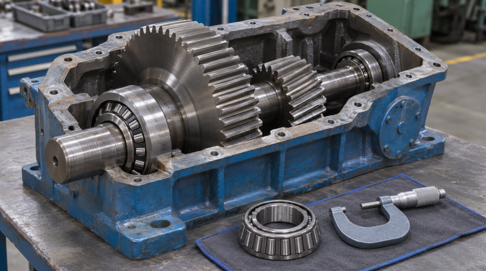
For example, if the output shaft bearing is damaged, but the journal, seat bore, and tooth surface all meet the acceptance requirements for this model and can be evaluated as a partial repair. If there are traces of running on the outer ring of the bearing, the seat hole measurement is also very poor, and simply replacing the bearing will leave a matching problem. If the tooth surface wear marks are biased towards one end at the same time, the position of the shaft and the gear meshing must also be reviewed. When broken teeth or cracks are found, the gears meshing with them should be inspected, and the decision on whether to expand the scope of repair should be made in conjunction with flaw detection, fit size and tooth surface damage. Eskom’s “Grinder Reduction Chamber Maintenance Guide” Section 3.1.3–3.1.4
On the bench, check the assembly records first. Verify the applicable tooth side clearance, tooth surface contact, and bearing adjustment values according to the reduction gearbox model, and then check the test speed, load, and vibration records. Eskom’s mill reduction tank maintenance guidelines require recording no-load vibrations and prioritizing load tests when conditions permit. Specific tolerances and release limits shall be implemented in accordance with the corresponding model drawings, manuals or agreed acceptance documents. Eskom’s “Grinder Reduction Chamber Maintenance Guide” Section 3.1.4
After reloading, the entire main drive is verified with the belt material. Review the coupling alignment and then test the vehicle according to the equipment specifications. Under stable operating conditions with recorded material, feed volume and speed, check whether the original abnormal noise is reproduced, whether the oil temperature can be stabilized, whether the box vibration and main motor current meet the acceptance requirements, and whether the original leakage point has seeped oil again. If the bench is unloaded and stable, the on-site material will reproduce abnormalities. During the review, the on-site centering, grinding load and gear loading meshing should be considered at the same time. The data from this stable belt material was kept as a baseline so that the subsequent retest could provide comparable working conditions. How Clirik Raymond Mills Work · NASA Equipment Condition Monitoring Guide